Analog IO
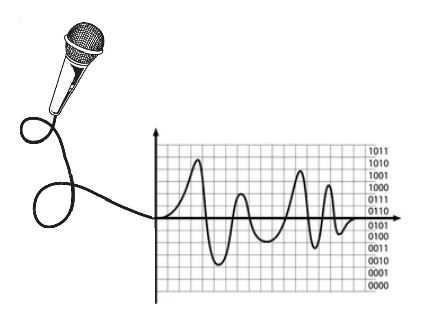
The Arduino can input and output analog signals as well as digital signals. An analog signal is one that can take on any number of values, unlike a digital signal which has only two values: HIGH and LOW.
Analog input in code: analogRead():
To measure the value of analog signals, the Arduino has a built-in analog-to-digital converter (ADC). The ADC turns the analog voltage into a digital value.
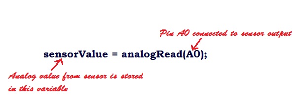
The function that you use to obtain the value of an analog signal is analogRead(pin). This function converts the value of the voltage (0-5v) on an analog input pin and returns a digital value from 0 to 1023.
Analog Sensor
The sensors that produce continuous analog output signal these are considered as analog sensors. There are various types of analog sensors such as temperature, moisture, accelerometer, pressure, light, sound sensor etc.

Adjusting values: map():
Writing value to pin: analogWrite():
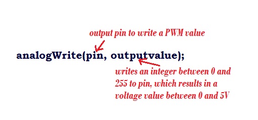
The Arduino does not have a built-in digital-to-analog converter (DAC), but it can pulse-width modulate (PWM) a digital signal to achieve some of the functions of an analog output. The function used to output a PWM (pulse width modulation) signal is analogWrite(pin, value). pin is the pin number used for the PWM output. value is a number proportional to the duty cycle of the signal. When value = 0, the signal is always off. When value = 255, the signal is always on. On most Arduino boards, the PWM function is available on pins 3, 5, 6, 9, 10, and 11. The frequency of the PWM signal on most pins is approximately 490 Hz.
Switch case (Contorl Structure):
Similar to the if statements, switch...case controls the flow of programs by allowing the programmers to specify different codes that should be executed in various conditions.
Syntax:

switch (variable)

{

case label1:

{

// statements

break;

}

case label2:

{

// statements

break;

}

default:

{

// statements

break;

}

}
Learning Objectives:
1. Be able to identify a potentiometer and know its value can be adjusted.
2. Write an Arduino sketch that can use an analog pin to read the position of a potentiometer and print the value in serial monitor.
3. Write a sketch that generates a series of pulses. Use these pulses to set the brightness level of a light-emitting diode (LED).
4. Write a sketch that allows a user to control the brightness of an LED by turning a potentiometer.
4. Know about LDR (Light Dependent resistor) and Write a sketch to read LDR signal .
Task List
| Sl.no | Task and Code Reference |
|---|---|
| 1 | Know the potentiometer.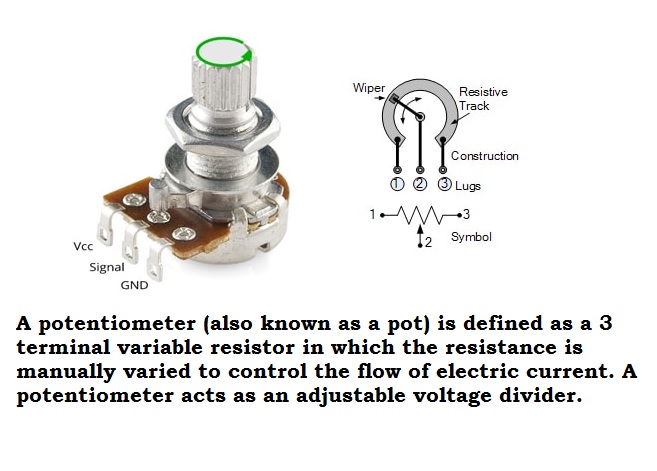 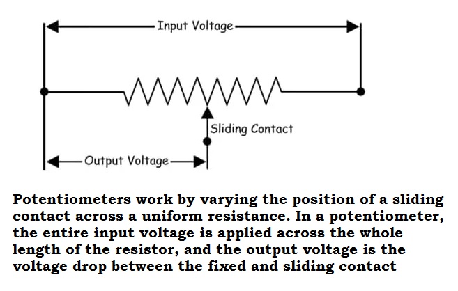 |
| 2 | Read the potentiometer.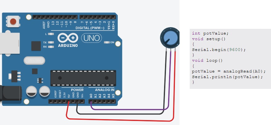 |
| 3 | Control brightness of LED.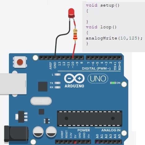 |
| 4 | Control brightness of LED using potentiometer.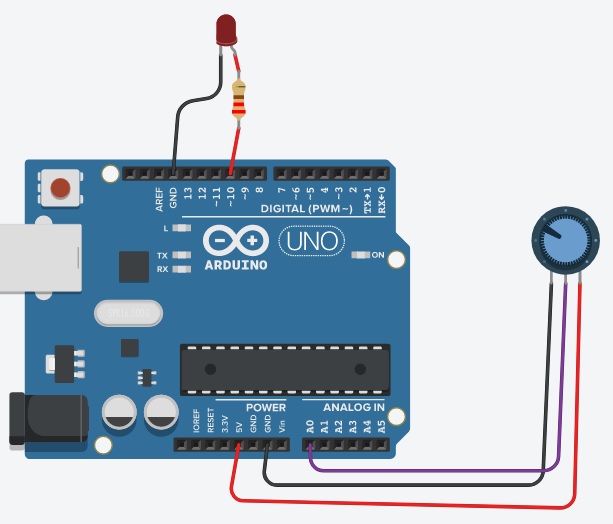 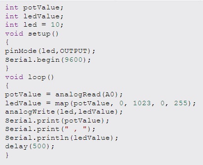 Try It View |
| 5 | Read LDR signal.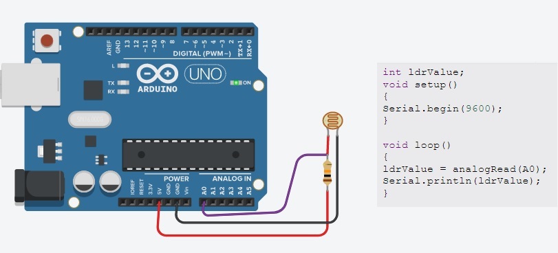 Try It View |
| 6 | Switch Case Demo Try It View |
Vocabulary
Analog Signal: Analog signal is a continuously variable signal, in contrast to digital signal where signals usually take only two levels.
Analog Sensor: The sensors that produce continuous analog output signal these are considered as analog sensors.
Mapping: The determination of a number within a range based on another number and its range.
ADC: Analog-to-digital converters, abbreviated as "ADCs," work to convert analog (continuous, infinitely variable) signals to digital (discrete-time, discrete-amplitude) signals.
PWM: Pulse Width Modulation, or PWM, is a technique for getting analog results with digital means. Digital control is used to create a square wave, a signal switched between on and off.
Pulse: The setting of a pin from LOW to HIGH for a speciic time then returning it to LOW.
Pulse width: The length of time a pulse is HIGH.
Potentiometer: A variable resistor,It provides a variable resistance when the shaft of the device is turned.
LDR:An LDR (Light Dependent Resistor) is a component that has a (variable) resistance that changes with the light intensity that falls upon it. This allows them to be used in light sensing circuits. A photoresistor is made of a high resistance semiconductor.