Arduino Hardware:
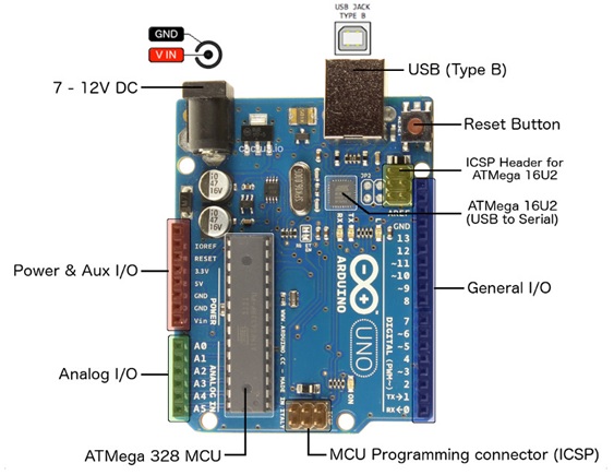
Digital I/O Pins: In Arduino Uno board 14 Digital I/O Pins. The 14 Digital I/O Pins are numbered from Pin 0 to Pin 13. In which 6 of them are PWM (Pulse-Width Modulation) Digital I/O Pins. Pin no 3, 5, 6, 9, 10, and 11 are PWM Pins which are marked as (~) symbol on the board. PWM pins are used to simulate analog output. Digital I/O Pins are used to take Digital Input or provide Digital Output in Arduino Uno Board.The maximum current draw from digital pin is 40 mA.
Analog Input Pins: In Arduino Uno board 6 Analog Input Pins. The 6 Analog Input Pins are numbered from Pin A0 to Pin A5. Analog Input Pins are used to take the signal from analog sensors and convert it into a digital value.
The Microcontroller:
It is important to understand that the Arduino board includes a microcontroller, and this microcontroller is what executes the instructions in your program. If you know this, you won't use the common nonsense phrase "Arduino is a microcontroller" ever again.
The ATmega328 microcontroller is the MCU used in Arduino UNO R3 as a main controller. ATmega328 is an MCU from the AVR family; it is an 8-bit device, which means that its data-bus architecture and internal registers are designed to handle 8 parallel data signals.
ATmega328 has three types of memory:
Flash memory: 32KB nonvolatile memory. This is used for storing application, which explains why you don't need to upload your application every time you unplug arduino from its power source.
SRAM memory: 2KB volatile memory. This is used for storing variables used by the application while it's running.
EEPROM memory: 1KB nonvolatile memory. This can be used to store data that must be available even after the board is powered down and then powered up again.
Power Pins:
Vin – The input voltage to the Arduino board when it’s using an external power source.
5V – This pin outputs a regulated 5V from the regulator on the board.The maximum current draw from this pin is 500 mA.
3V3 – This pin outputs a regulated 3.3 volt supply generated by the onboard regulator. The maximum current draw from this pin is 50 mA.
GND – Ground pins.
USB Connector: – USB connector is used for two purposes in Arduino. The first one is to load the user program to Arduino using Arduino IDE and another one is to power Arduino Board.
Arduino CPU frequency:The Arduino UNO makes use of the ATmega328 Processor which has an operating frequency of 16 MHz.
Arduino Software:
Software programs, called sketches, are created on a computer using the Arduino integrated development environment (IDE). The IDE enables you to write and edit code and convert this code into instructions that Arduino hardware understands. The IDE also transfers those instructions to the Arduino board (a process called uploading).
Learning Objectives:
1.Know the Arduino Software and Hardware.
2.Know the purpose of an Integrated Development Environment (IDE).
3. Know how to locate, download, and install the ArduinoIDE.
4.Setting up the Arduino board.
5. Uploading and running the example code.
6. Be able to modify, save, upload, and run simple sketches for the Arduino.
7. Know the Arduino programming Structure.
8. Be able to write a simple program for Arduino (sketch).
Task List
| Sl.no | Task and Code Reference |
|---|---|
| 1 | Download and install Arduino IDE 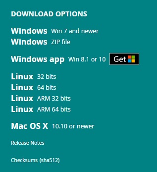 1.Visit: http://arduino.cc/en/Main/Software 2. Download "Windows win7 and newer" for Admin installation. 3.Download “Windows ZIP file for non Admin install”. 4. Extract the ZIP file and open .exe file. |
| 2 | Know the menu bar, tool bar, Sketch tabs, Code area and Status display: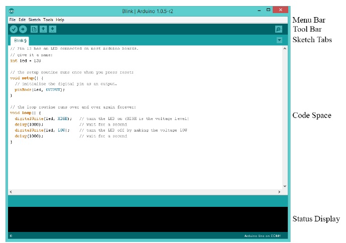 |
| 3 | Know the tool bar: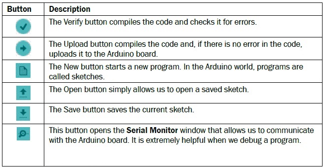 |
| 4 | Connect the Arduino to the computer using a USB cable.
(If everything is properly connected, the green LED light will turn on.)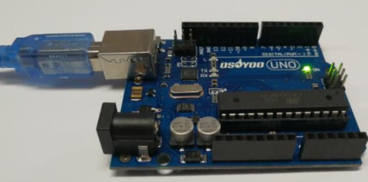 |
| 5 | Select the Arduino Uno board from menu.
The menu can be found in the Menu bar in Tools | Board.
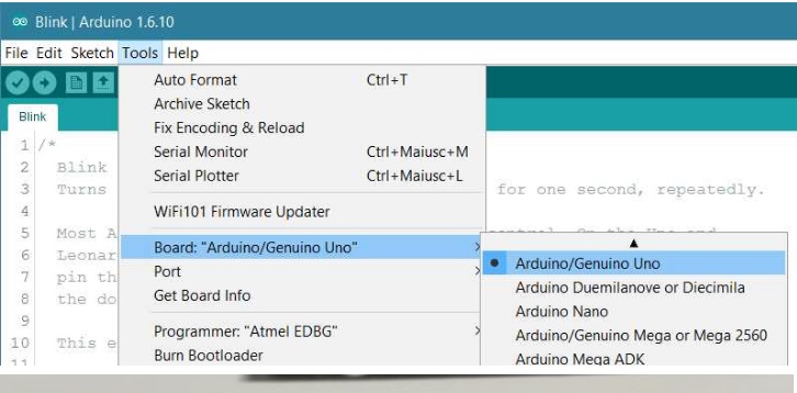 |
| 6 | Select the correct serial port from menu.
Tools | Serial Port
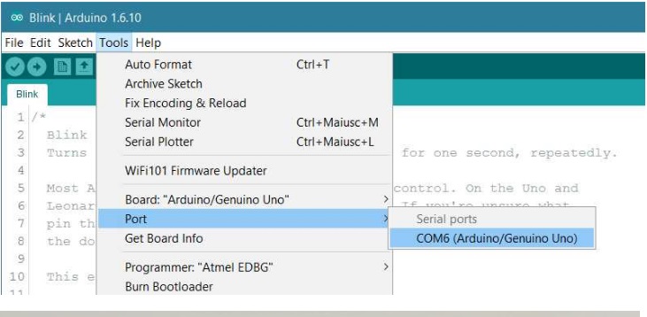 |
| 7 | Load built-in example sketch
Go to File | Examples | 01. Basics click on the Blink example.
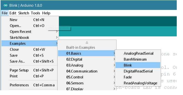 |
| 8 | Modify the Blink program to Blink in every 2 seconds. Upload the program:Now, simply click the "Upload" button in the environment. Wait a few seconds - you should see the RX and TX leds on the board flashing. If the upload is successful, the message "Done uploading." will appear in the status bar. 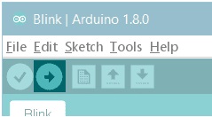 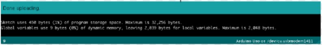 |
Lession-1 Vocabulary
Software: Software programs, called sketches, are created on a computer using the Arduino integrated development environment (IDE). The IDE enables you to write and edit code and convert this code into instructions that Arduino hardware understands.
Hardware: Arduino hardware is best described as any physical component of a computer system containing a circuit board, ICs, or other electronics.
Integrated Development Environment (IDE): A collection of computer programs used to create other computer programs. algorithm A means of or steps to performing a specific task. For a computer, an algorithm is usually expressed in a set of computer program instructions.
Arduino: A single-board computer and an open-source electronics platform based on easy-to-use hardware and software. It's intended for anyone making interactive projects. The term single-board means that the entire computer it’s on a single circuit board.
C programming language: The programming language used to write sketches for the Arduino™ SBC. The syntax is similar to several other commonly used programminglanguages, including C++, C#, and Java.
microcontroller: A complete self-contained computer in a chip, including the memory for a program and its data. This small microprocessor also contains the necessary electronics to communicate with external devices.
microprocessor: A complex electronic integrated circuit that performs the processing tasks of a computer, including input, output, and computation.
Single-board computer (SBC): An entire microcomputer on a single printed circuit board. Abbreviated SBC. Examples includethe Arduino™ and the Raspberry Pi. sketch A computer program written for the Arduino™.
Input: To receive information from the outside world. Examples: Keyboard, mouse, network connection,touch screen, voltage sensor
Output: Information of any sort that comes out of a computer to display information or to control devices. Examples: Monitor, lights, printer, motor, network connection
Processor: To manipulate information. Examples: Intel Core i5, Atmel ATmega 328
Storage: To contain programs to be run and data to be accessed. Examples: Memory, hard disk, cloud storage.
sketch: A collection of instructions for your Arduino.
Keywords: some words have special meaning to the C language as it is used with the Arduino. these are called keywords. A keyword cannot be used for any other purpose. Examples: void, loop, setup, for, if, if-else, while etc.
Method or function: A collection of C-language statements that perform a specific task. A method always has a name. Some methods can receive and return data.
Programming statement: A computer language instruction. A set of pre-written C-language instructions that are used to send and receive data via a serial port.
Comment: Text inside a sketch that is present to provide the human reader of the sketch insight into some aspect of the sketch's operation but that is ignored by the Arduino.