Diode
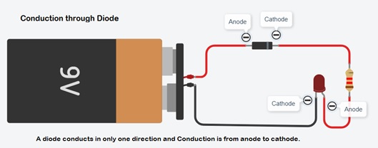
A diode is made of silicon. Silicon is neither an insulator nor a conductor. It is a semiconductor. A diode functions as the electronic version of a one-way valve. By restricting the direction of movement of charge carriers, it allows an electric current to flow in one direction, but blocks it in the opposite direction.
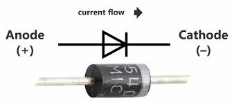
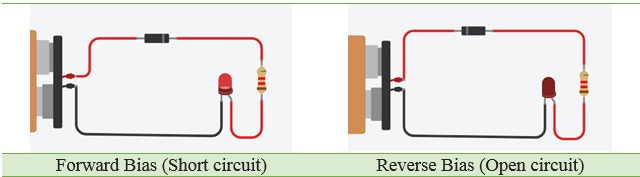
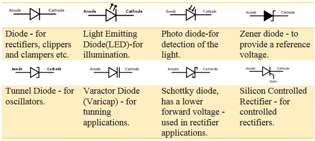
Diode is made of P and N type materials and has two terminals namely anode and cathode. This device can be operated by controlling the voltage applied to these terminals. When the voltage applied to the anode is positive with respect to the cathode, the diode is said to be in Forward Bias. If the voltage applied to the diode is greater than the threshold level (generally, it is of ≈0.6V for Silicon Diodes), then diode acts as a short circuit and allows the current flow. If the polarity of the voltage is changed i.e., the cathode is made positive with respect to anode, then it is said to be in Reverse Bias and acts as open circuit. As a result, no current flows through it.
Since electricity can only flow in one direction through a diode they must be connected correctly. Electrical current flows from the cathode side of a diode to the anode side. Generally the cathode side is connected to the negative side of a DC power supply. A diode has a black band marking the cathode side.
Voltage drop across diode:
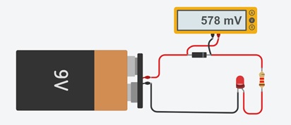
A forward biased diode has a voltage drop of about 0.7 V. This voltage drop is called the forward voltage drop.
How to Test Diodes with a Digital Multi-meter:
Digital multi-meters can test diodes using one of two methods:
1.Diode Test mode: almost always the best approach.
2.Resistance mode: typically used only if a multi-meter is not equipped with a Diode Test mode.
Note: In some cases it may be necessary to remove one end of the diode from the circuit in order to test the diode.
A diode is best tested by measuring the voltage drop across the diode when it is forward-biased. A forward-biased diode acts as a closed switch, permitting current to flow. A multi-meter's Diode Test mode produces a small voltage between test leads. The multi-meter then displays the voltage drop when the test leads are connected across a diode when forward-biased.
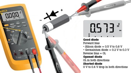
A multi-meter set to the Resistance mode (Ω) can be used as an additional diode test or, as mentioned previously, if a multi-meter does not include the Diode Test mode.
Diodes applications:
The application areas of diodes include communication systems as limiters, clippers, gates; computer systems as logic gates, clampers; power supply systems as rectifiers and inverters; television systems as phase detectors, limiters, clampers; radar circuits as gain control circuits, parameter amplifiers, etc.
Diode as Rectifier:
This circuit is used to transform AC waveform into DC waveform.

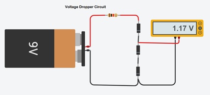
Voltage Dropper Circuit:
This circuit will drop the power supply voltage by ≈0.6V per diode.
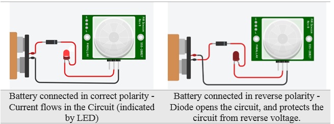
Reverse polarity protector:
Diode protects circuit if battery is installed with reverse polarity.
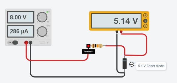
Zener diode voltage regulator:
Zener diodes are widely used as voltage references and as shunt regulators to regulate the voltage across small circuits. When connected in parallel with a variable voltage source so that it is reverse biased, a Zener diode conducts when the voltage reaches the diode's reverse breakdown voltage. From that point on, the low impedance of the diode keeps the voltage across the diode at that value.
The Zener diode behaves just like a normal general-purpose diode consisting of a silicon PN junction and when biased in the forward direction, that is Anode positive with respect to its Cathode, it behaves just like a normal signal diode passing the rated current.