Integrated Circuits (ICs)
Integrated circuit:
Integrated circuit (IC), also called microelectronic circuit, microchip, or chip, an assembly of electronic components, fabricated as a single unit, in which miniaturized active devices (e.g., transistors and diodes) and passive devices (e.g., capacitors and resistors) and their interconnections are built up on a thin substrate of semiconductor material (typically silicon). The resulting circuit is thus a small monolithic “chip,” which may be as small as a few square centimetres or only a few square millimetres. The individual circuit components are generally microscopic in size.
The advantages of ICs:
(i) Extremely small in size, (ii) Low power consumption, (iii) Reliability, (iv) Reduced cost, (v) Very small weight and (vi) Easy replacement.
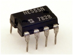
The 555 IC:
The 555 timer is an integrated circuit, it is extremely versatile and can be used to build lots of different circuits.The EN555 is usually used to generate continuous series of pulses. These series of pulses allow you to continuously blink an LED, for example.
The 555 timer IC was first introduced around 1971 by the Signetics Corporation as the SE555/NE555 and was called "The IC Time Machine" and was also the very first and only commercial timer IC available. It provided circuit designers with a relatively cheap, stable, and user-friendly integrated circuit for both monostable and astable applications.
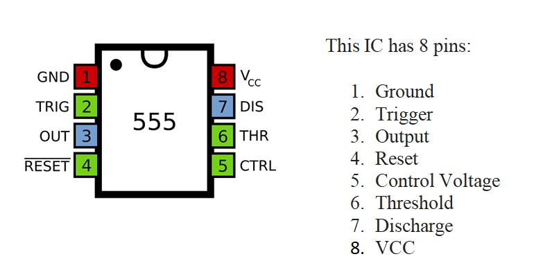
Pin Diagram:
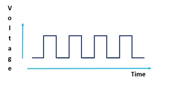
Output :
Pin 3 is the output. This pin generates an oscillation. The voltage is high, then low, then high, then low again and so on (this is called astable mode).
ICs and Datasheets
Some ICs have only 8 pins, but other ICs have more than 100! To figure out what each pin on a specific IC does, you need to check that IC's datasheet. The datasheet tells you the function of each pin, specifications and datasheets often show examples of how to use ICs in a circuit, too.
Specifications of the 555 IC timer:
- It operates from a wide range of power ranging from +5 Volts to +18 Volts supply voltage.
- Sinking or sourcing 200 mA of load current.
- The external components should be selected properly so that the timing intervals can be made into several minutes along with the frequencies exceeding several hundred kilohertz.
- The output of a 555 timer can drive a transistor-transistor logic (TTL) due to its high current output.
- It has a temperature stability of 50 parts per million (ppm) per degree Celsius change in temperature which is equivalent to 0.005 %/ °C.
- The duty cycle of the timer is adjustable.
- Also, the maximum power dissipation per package is 600 mW and its trigger and reset inputs has logic compatibility.
555 timer working:
The 555 generally operates in 3 modes:
Astable
Mono-stable
Bi-stable modes.
Astable mode:
This means there will be no stable level at the output. So the output will be swinging between high and low. This character of unstable output is used as a clock or square wave output for many applications.
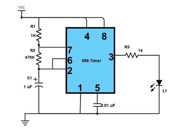
555 IC LED Flasher (Astable Mode):
Mono-stable mode:
This configuration consists of one stable and one unstable state. The stable state can be chosen either high or low by the user. If the stable output is set at high (1), the output of the timer is high (1). At the application of an interrupt, the timer output turns low (0). Since the low state is unstable it goes to high (1) automatically after the interrupt passes. Similar is the case for a low stable monostable mode.
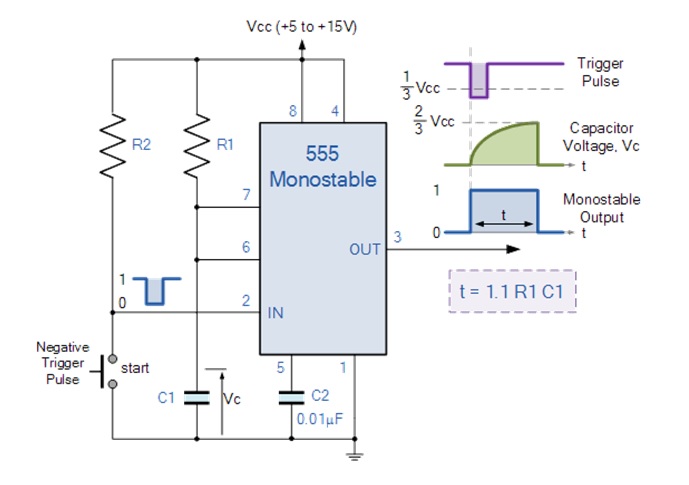
555 IC Timer circuit(Monostable Mode):
Bi-stable mode:
In bistable mode, both the output states are stable. At each interrupt, the output changes from low (0) to high (1) and vice versa, and stays there. For example, if we have a high (1) output, it will go low(0) once it receives an interrupt and stays low (0) till the next interrupt changes the status.
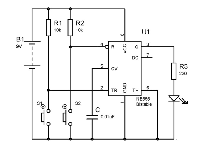
555 IC memory cell(Bi-stable Mode):
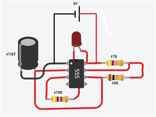
Electronic Fire-fly using555 IC
LM358 Dual Operational Amplifiers
The LM358 IC is a great, low power and easy to use dual channel op-amp IC. It is designed and introduced by national semiconductor. It consists of two internally frequency compensated, high gain, independent op-amps. This IC is designed for specially to operate from a single power supply over a wide range of voltages. The LM358 IC is available in a chip sized package and applications of this op amp include conventional op-amp circuits, DC gain blocks and transducer amplifiers. LM358 IC is a good, standard operational amplifier and it is suitable for your needs. It can handle 3-32V DC supply & source up to 20mA per channel.
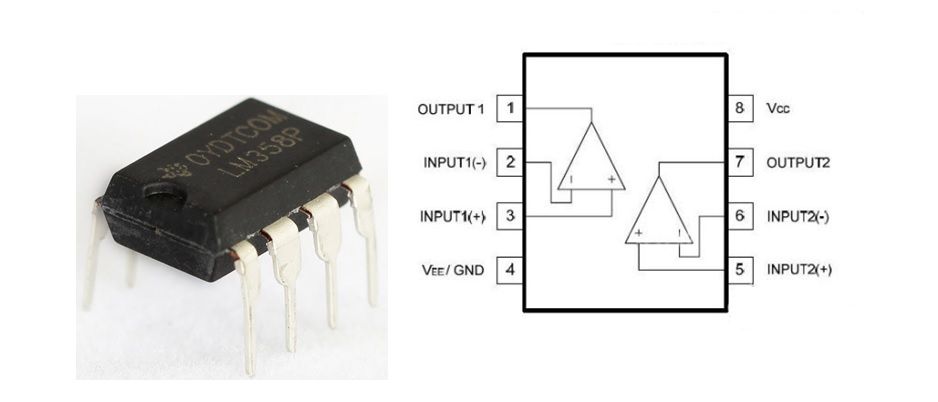
Pin Configuration of LM358 IC
The pin diagram of LM358 IC comprises of 8 pins, where
- Pin-1 and pin-8 are o/p of the comparator
- Pin-2 and pin-6 are inverting inputs
- Pin-3 and pin-5 are non inverting inputs
- Pin-4 is GND terminal
- Pin-8 is VCC+
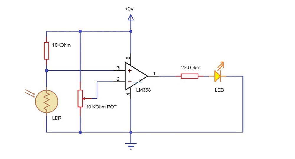
Light Detector using LM358