Measuring Electrical Parameters
A meter is any device built to accurately detect and display an electrical quantity in a form readable by a human being. Usually this "readable form" is visual: motion of a pointer on a scale, a series of lights arranged to form a "bargraph," or some sort of display composed of numerical figures.
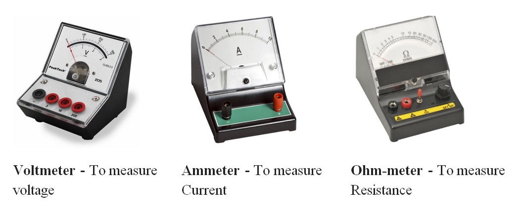
In the analysis and testing of circuits, there are meters designed to accurately measure the basic quantities of voltage, current, and resistance.
These three metering functions are combined into a single meter called a "Multi-meter". A multi-meter, also known as a volt-ohm meter, is a handheld tester used to measure electrical voltage, current (amperage), resistance, and other values.
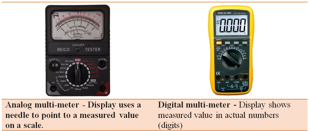
Multi-meters come in analog and digital versions and are useful for everything from simple tests, like measuring battery voltage, to detecting faults and complex diagnostics. They are one of the tools preferred by electricians for troubleshooting electrical problems on motors, appliances, circuits, power supplies, and wiring systems.
Multi-meter Functions
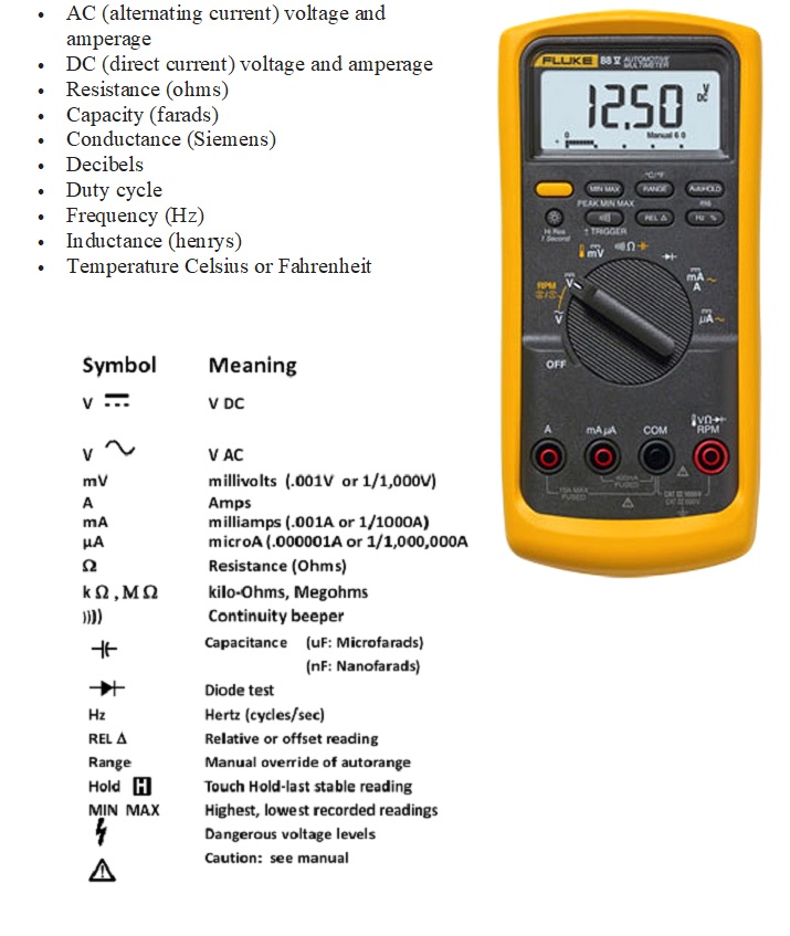
Multi-meters are capable of many different readings, depending on the model. Basic testers measure voltage, amperage, and resistance and can be used to check continuity, a simple test to verify a complete circuit. More advanced multi-meters may test for all of the following values:
Multi-meter Parts
The multi-meter consists of a digital display, mode selector, range selector, various buttons, test probes & input jacks.
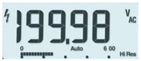
Digital display: The digital display gives a direct readout in actual numbers. However, we must properly interpret to get the correct measured value (i.e Voltage type-AC/DC voltage, Range- mV/mA/V/A and Units - Ohms, V and A etc.
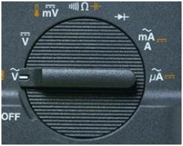
Mode Selector: Mode selector is used to set the meter for the type of test to be performed (i.e DC Volts, AC Volts, milli Volts, Resistance, Continuity test, Diode Check, milli Amps etc)
Range selection & Various Buttons:
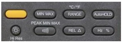
Function button: Yellow button activates secondary functions shown in yellow icons around the dial (often temperature and capacitance).
Min Max: Stores input values; beeps when a value is breached and a new value is set. Peak Min Max: Captures intermittent or transient events that occur on a monitored signal; captures the highest value in a very short duration (microseconds).
Range: Switches to manual mode and cycles through all ranges. Auto ranging restored when pressed for two seconds.
Hold: Captures and holds a stable measurement. AutoHOLD: Captures a measurement, beeps, and locks the measurement on the display for later viewing. Automatically updates with a new stable reading.
Brightness: Switches display backlight between off, low and high.
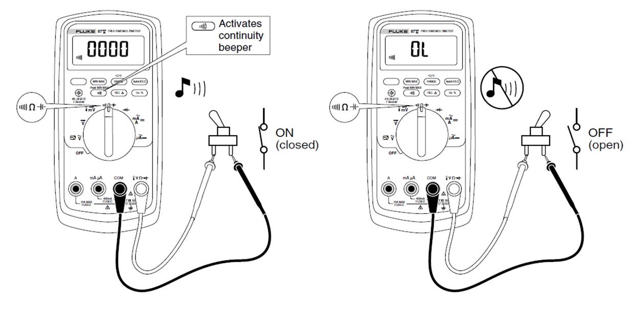
Audible signal: Activates continuity beeper.
Relative (REL) mode: Stores existing reading (a delta) and resets display to zero. Sets a relative reference point to measure against the next reading.
Test Probes and Input Jacks:
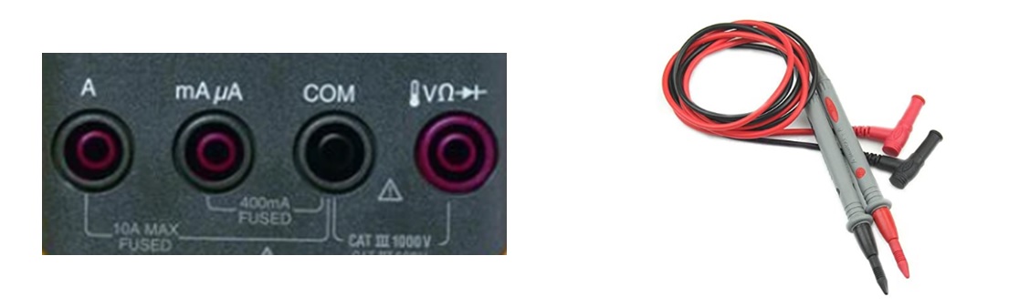
The typical DMM has two test leads and four input jacks. The leads plug in as follows:
BLACK: always plug into the COM input jack.
RED: Plug into the one of the three remaining jacks, depending on what measurement is being performed.
- V/Ω/Diode input for measuring voltage, resistance and Diode checking.
- A input for measuring current upto 10 amps.
- μA/mA input for measuring current upto 400mA.
Measuring voltage
Voltage measurements are made by connecting the DMM in parallel with the measuring point.
If you're measuring DC voltage (such as a battery or a sensor hooked up to an Arduino) you want to set the knob where the V has a straight line (i.e DC). AC voltage (like what comes out of the wall) can be dangerous, so we rarely need to use the AC voltage.
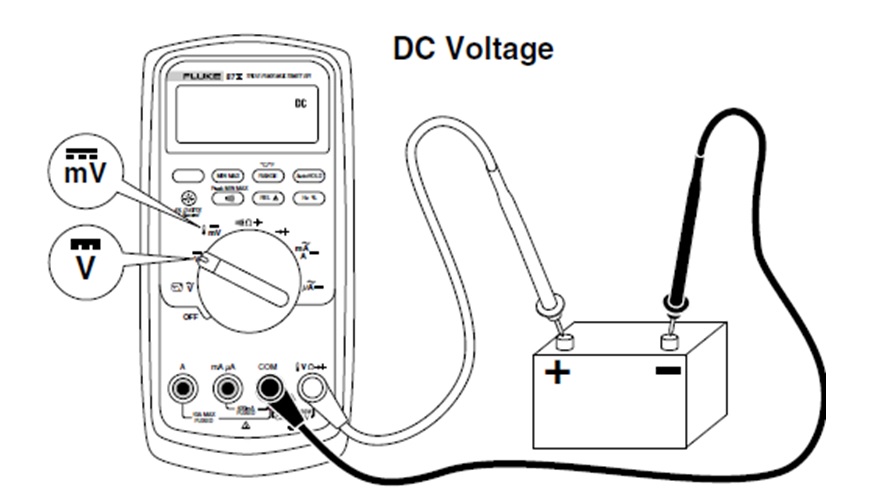
When we place the probes of a DMM on the terminals of a battery, we are measuring electromotive force or Voltage, between the positive and negative battery terminals.
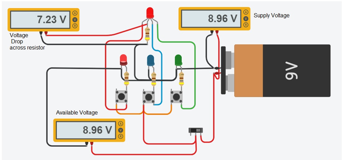
Voltage measurement applications: Technicians are concerned with the voltage in different applications:
- Source Voltage : to measure the supply voltage
- Available Voltage : to measure available voltage in the circuit.
- Voltage drop: to measure voltage drop across components.
We can measure voltage...
Between any two points in a circuit.
Between any point in a circuit and ground.
Across any component in the circuit.
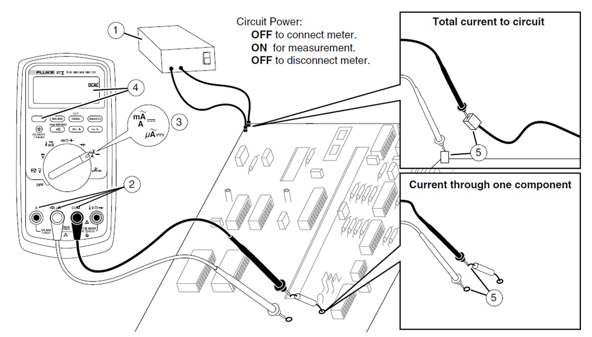
Measuring AC or DC Current
The rate at which electrons flow, i.e., current through a conductor is measured using an ammeter. To perform the measurement of current using ammeter, the circuit must be opened and then the meter is inserted in series or in-line with the circuit as shown in figure.
Caution:
Never place the probes across (in parallel with) any circuit or component when the leads are plugged into the current terminals.
Never leave the multimeter in ammeter position once the current measurement is taken.
Don't test higher currents than that of highest current measured by the multimeter in their respective ranges, i.e., mA as well as A range.
Measurement of Current with Clamp Meter
It may be difficult to open a circuit to connect in-line ammeter to measure the current. A new type of test tool that overcomes such problem is the clamp meter which comes with clamp-on current probe with multi-meter.
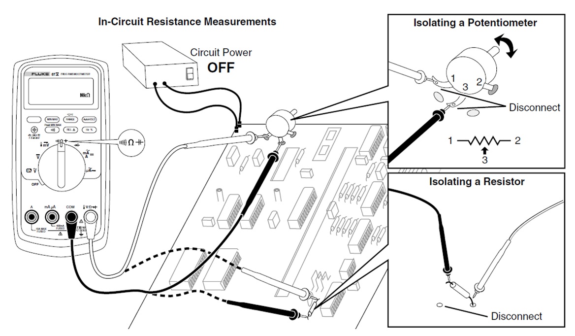
Measuring Resistance
The Meter measures resistance by sending a small current through the circuit. Because this current flows through all possible paths between the probes, the resistance reading represents the total resistance of all paths between the probes.
Testing for Continuity
The continuity test features a beeper that sounds as long as a circuit is complete. The beeper allows you to perform quick continuity tests without having to watch the display.
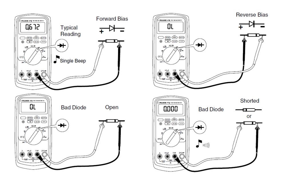
Testing Diodes
To check a diode, use the diode check function on the meter and apply both forward and reverse bias. Use the diode test to check diodes, transistors, silicon controlled rectifiers (SCRs), and other semiconductor devices. This function tests a semiconductor junction by sending a current through the junction, then measuring the junction's voltage drop. A good silicon junction drops between 0.5 V and 0.8 V.