Resistors
Various components, such as the LED, require only a small amount of current to function—usually around 10 mA. When the LED receives excess current, it converts the excess to heat—too much of which can kill an LED. To reduce the flow of current to components such as LEDs, we can add a resistor between the voltage source and the component. Current flows freely along normal copper wire, but when it encounters a resistor, its movement is slowed. Some current is converted into a small amount of heat energy, which is proportional to the value of the resistor.
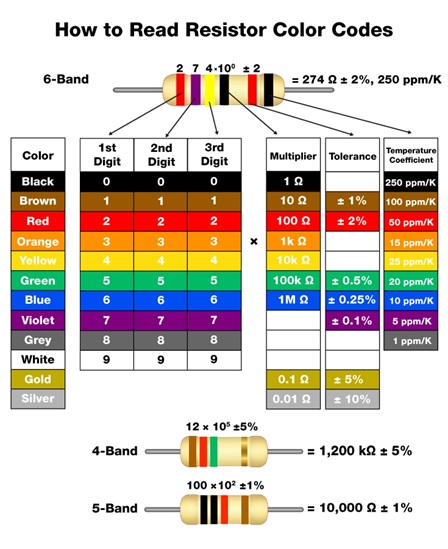
Resistors - A resistor is a component that adds resistance to a circuit. The more resistance your circuit has, the less current will flow through it. Resist the flow of electrical energy in a circuit, changing the voltage and current as a result. Resistor values are measured in ohms (represented by the Greek omega char¬acter: Ω). The colored stripes on the sides of resistors indicate their value.
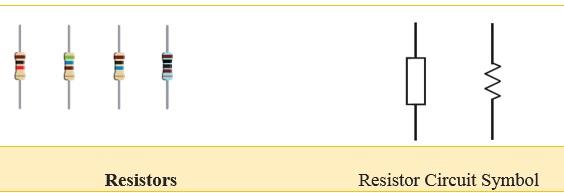
The photo shows a typical fixed resistor. Resistors of this kind are sold in a range of different resistances, from less than 1 Ω and up to 10MΩ.
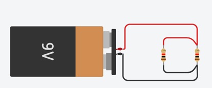
Resistors in Series:
A set of resistors are said to be in series when they are connected back to back in a single line. The same current will flow through all the resistors. Resistors in series are said to have common current.
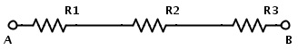
If RT is the total resistance, then RT = R1 +R2 +R3
Applications:
When two resistors of different resistances are connected in series, the voltage across them is different. This method is the basis for voltage divider circuits.
Voltage Divider Circuit:
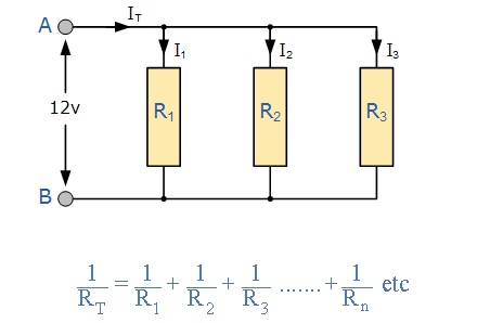
Resistors in Parallel:
Two resistors are said to be connected in parallel if both the terminals of a resistor are connected to each respective terminal of other resistor. In a network of parallel resistors, current can take more than one path unlike in series resistor network as there are multiple paths for the current to flow. Hence parallel resistor circuits are current dividers.
Applications:
The concept of resistors in parallel is used in the analysis of Wheatstone bridge circuit. Resistors in parallel combination act as Current Divider Circuit. This current divider concept is use full in applications like Analog to Digital Converters and Digital to Analog Converters.
Current Divider Circuit::
Variable Resistors
Variable resistors consist of a resistance track with connections at both ends and a wiper which moves along the track as you turn the spindle. The track may be made from carbon, cermet (ceramic and metal mixture) or a coil of wire (for low resistances). The track is usually rotary but straight track versions, usually called sliders, are also available.
A Variable Resistor may be used instead of a fixed resistor where variable resistance is required.
A Variable Resistor is a useful device, because by just simply adjusting it, it can be used to represent a wide range of resistances in a circuit from anywhere near 0Ω to the specified resistance rating of the potentiometer. Therefore, for example, a 10KΩ potentiometer can be adjusted to give the resistance range from almost 0Ω to 10KΩ by adjusting the potentiometer knob.
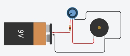
Volume Control Circuit (potentiometer):
Variable resistors used as potentiometers have all three terminals connected. This arrangement is normally used to vary voltage.
LED Brightness Control (Rheostat):
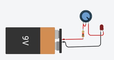
This is the simplest way of using a variable resistor. Two terminals are used. Rheostats are often used to vary current.